ATTACHMENT OF AXLES: Hone holes for axles to give a tight
sliding fit for the two stub axles. Press axles into the holes
and secure them with the 5/8-inch screws provided. Torque the
bolts to 150 lb-ft. Test orientation of axle by using dial indicator
on height gauge to measure runout of axle flange with respect to
attachment plate.
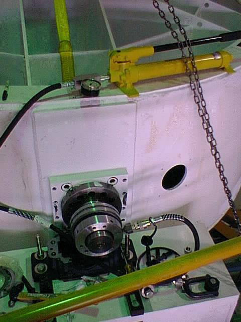
ATTACHMENT OF BEARINGS: Measure bearing slack with feeler gauges.
Calculate distance onto tapered shaft to remove slack, using the
rule of thumb from ... Make sure seals are on axles, then slide
bearing and tapered sleeve onto axle. Use hydraulic pump to
push bearing onto tapered shaft by the
amount calculated to remove slack. Incidently, this mounting of the
bearings is contrary to recommendations of the manufacturers in that
they have no slack to allow for manufacturing defects.
AT THE OBSERVATORY
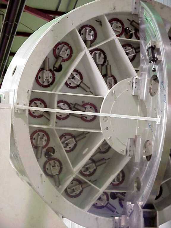
Assemble 30 of the axial supports (support levers)
into base of tube, leaving six holes free for the lifting slings. Screw hard
points into the tube.
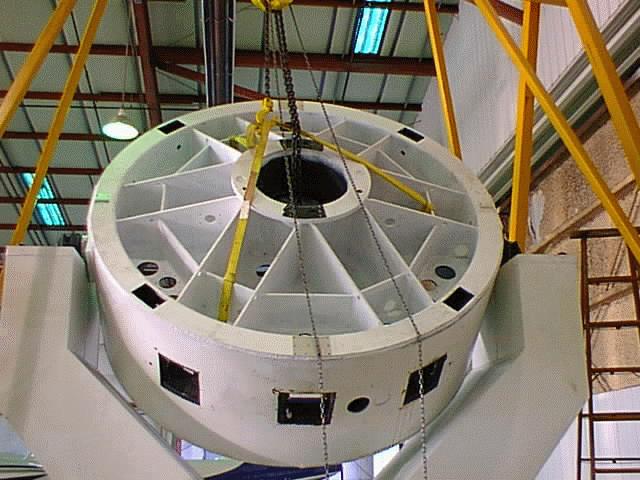
Pick up tube with crane, using three 6-foot slings attached through
the axial-support and lifting holes in three particular box sections of
the back web of the cell. The slings should go
through the three old lifting holes 60 degrees from the hard points. Lift the
cell and place it directly above the fork.
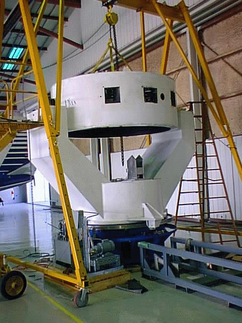
Orient the tube with pillow blocks above attachment points on the fork.
Lower pillow blocks onto the tines, using guides provided to ease in place. Put
the 0.010-inch shims in place under the pillow block on the low tyne. Orient
pillow blocks and torque bolts to appx 150 lb-ft. Torque lateral supports
for pillow blocks to 50 lb-ft.
[Rotate cell >180 degrees to verify motion. Without the lateral/axial
supports, the cell would be bottom heavy by about 500 lb-ft.]
Secure the cell with the temporary stay bar. Add the six remaining
axial-support levers while the cell is still inverted. Add the
tilt-drive sector (see separate procedure), then rotate the tube to
its upright position. Secure with the 90-degree stay bar. Assemble the lateral-support levers into the cell. To do this (1) lower each 50-lb
weight into its pocket with a 1/2-inch threaded rod with a cross handle. Put
weight on side. Run threaded lever arm through weight and attach with washer,
lock washer, and 3/4-in nut. Pull body of lever through hole in floor of cell
and attach side frames to it with set screws. Bolt side frames to cell (the
center push lever requires special shims), and attach devices for attaching to
mirror (either push rods or pull rods). Note: The pull levers must be
disassembled to get the pull rods into place.