Construction of Telescope Mount:TSU
chose the manufacturing center at ORNL to build the telescope mount
in July, 1997. Construction proceeded steadily at ORNL and at
other machine shops making various smaller parts of the telescope mount.
- Autocad drawing of
Telescope Mount.
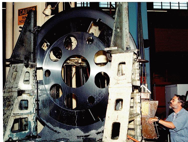
- Telescope base
at ORNL, July, 1997.
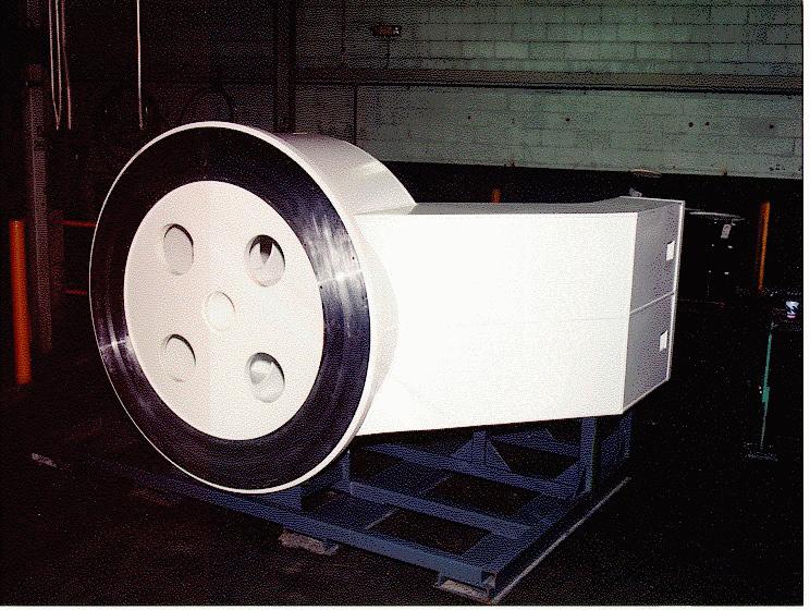
- Telescope fork
under construction at ORNL, July 1997,
and after fabrication (side and top
views with Rick Craze and John Barnes of ORNL), October, 1997.
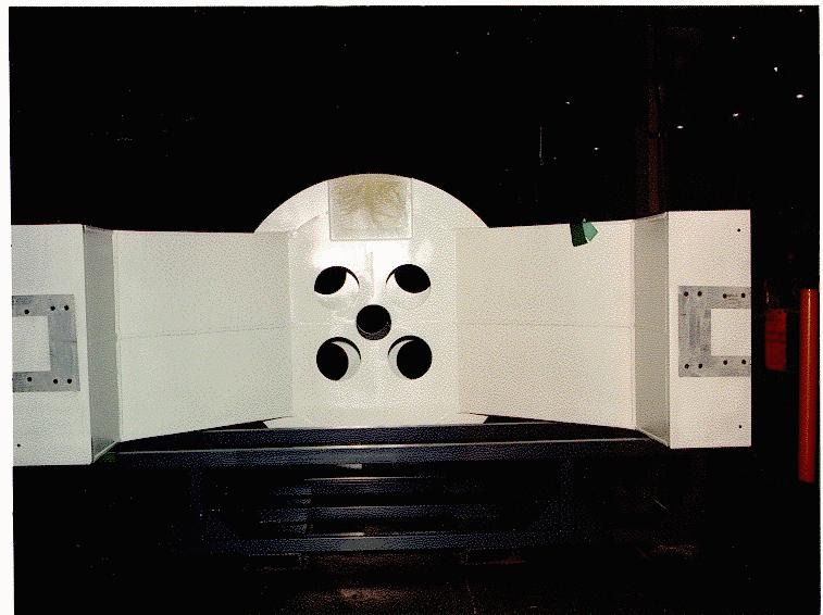
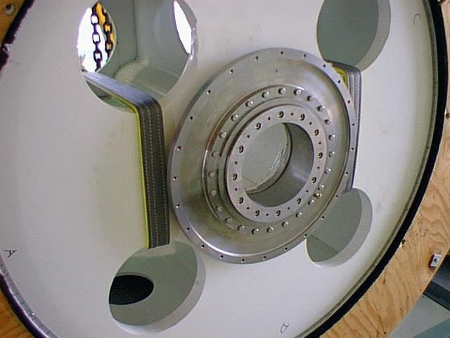
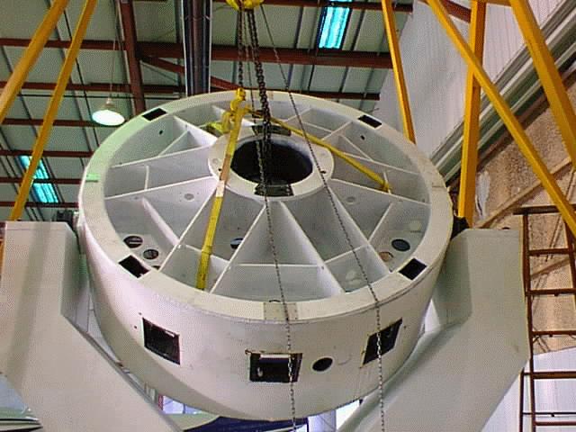
- Top plate
and base of telescope fork
(showing arrangement of internal plates), July 1997.
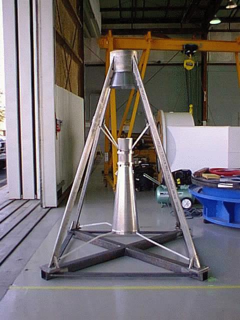
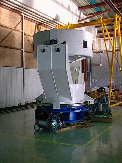
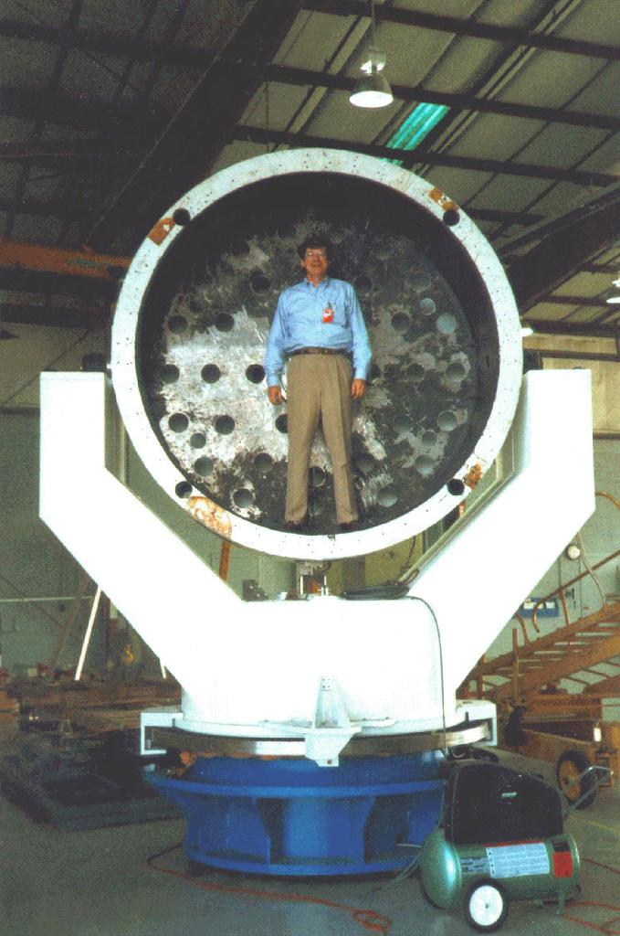
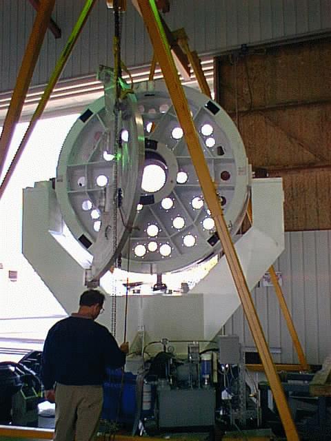
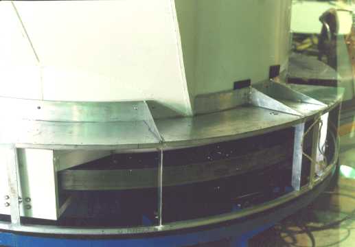
- Telescope fork as finished:
base showing bearing and
top views, June, 1998.
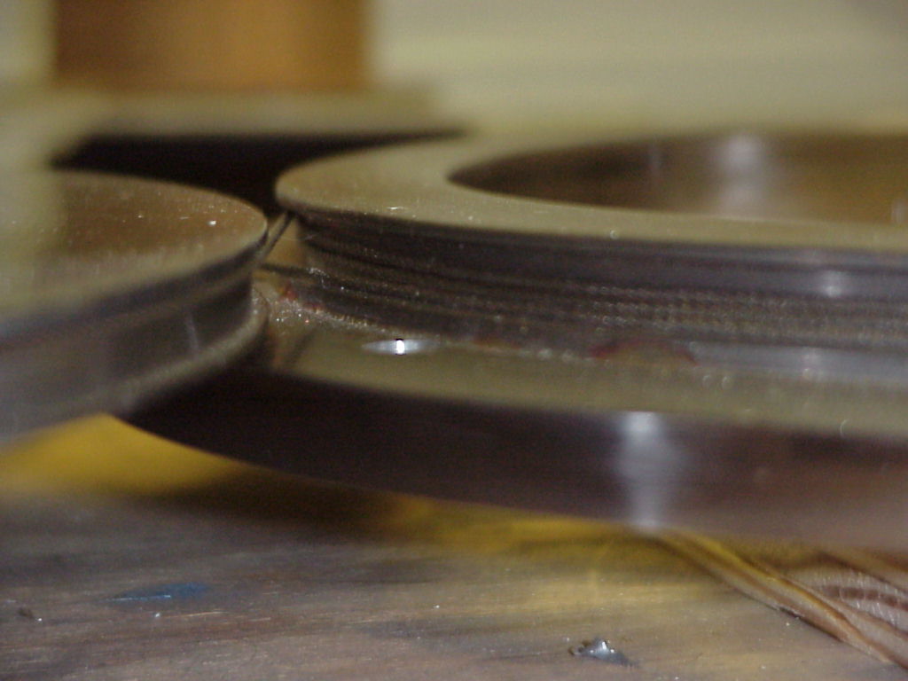
- Azimuth slewing ring
at ORNL, June, 1998.
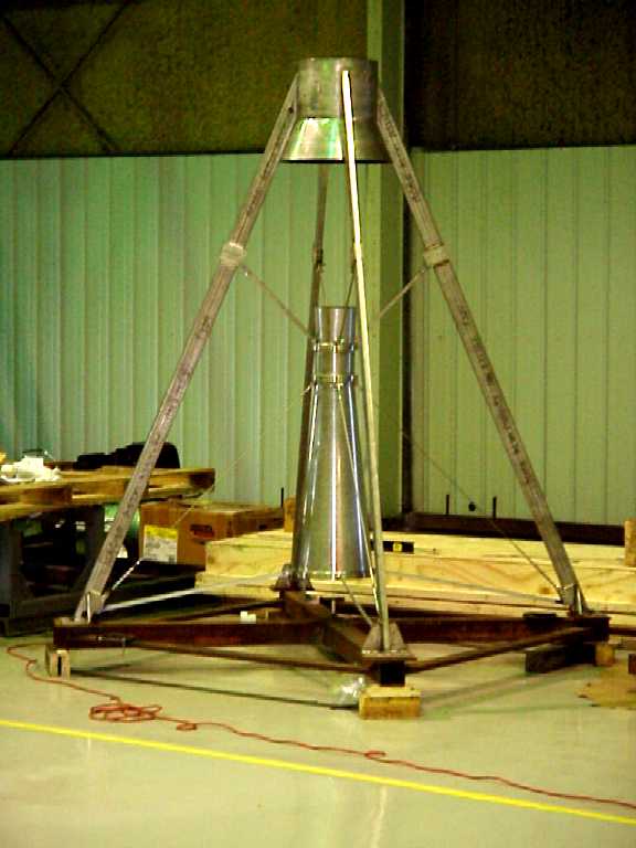
- Central pivot to constrain
telescope laterally (Schmiede Machine), August, 1998.
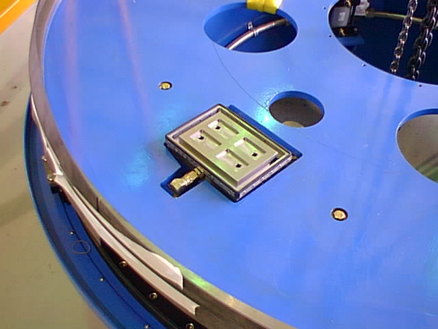
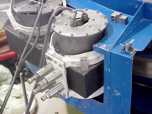
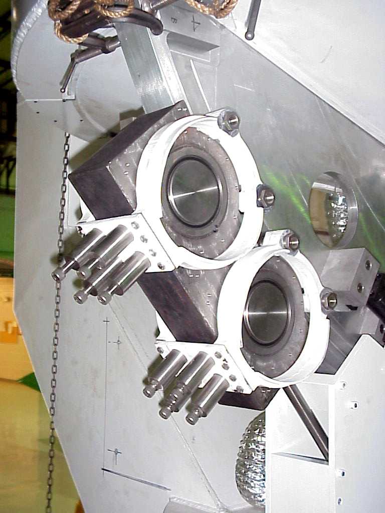
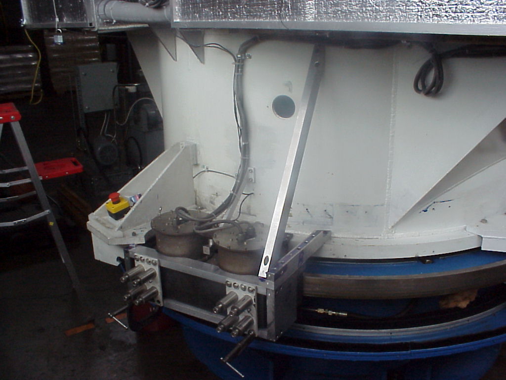
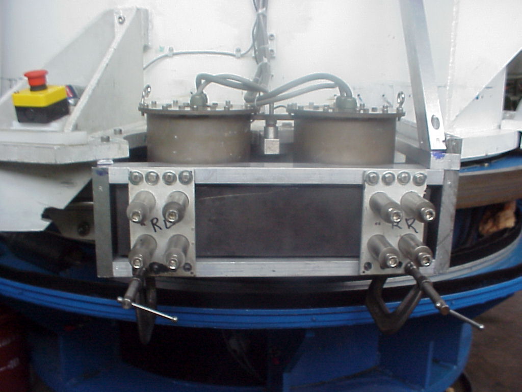
- Two of the oil pads
at ORNL, October, 1997, and
in the telescope, July, 1998.
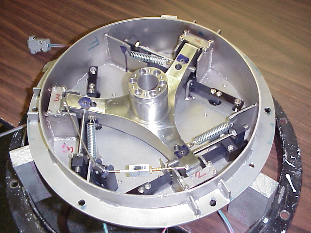
- Modification of mirror cell
at ORNL, July, 1998.
- Altitude axles, by Schmiede Machine
of Tullahoma, Tenn.
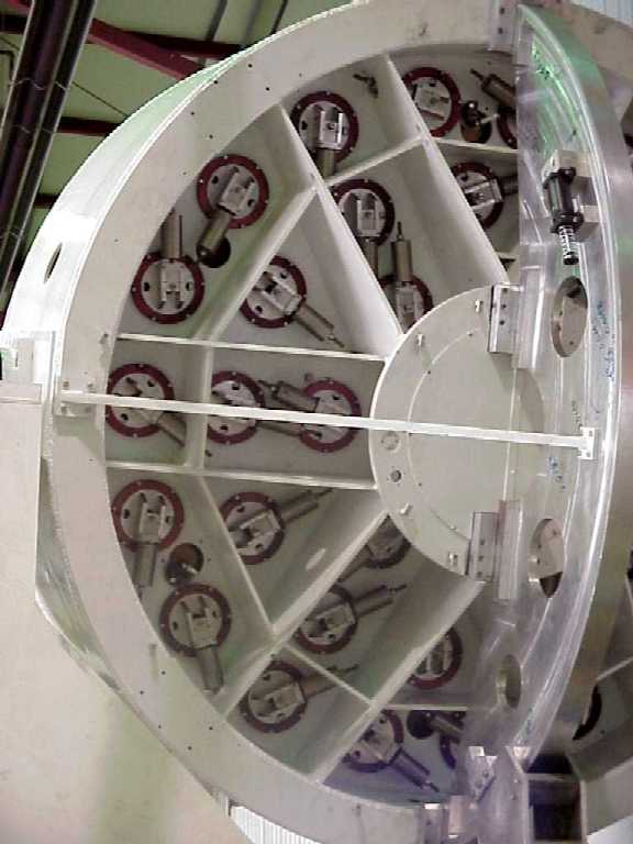
- Axial support levers
for the primary mirror, by Hamilton Machine of Nashville, Tenn.
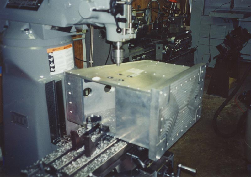
- Machining altitude slewing ring
at ORNL, July, 1998.
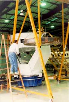
Integration of the 2-m Telescope:
We put the telescope together in Nashville, so as to correct any problems
with its mount and exercise its control system before transporting it
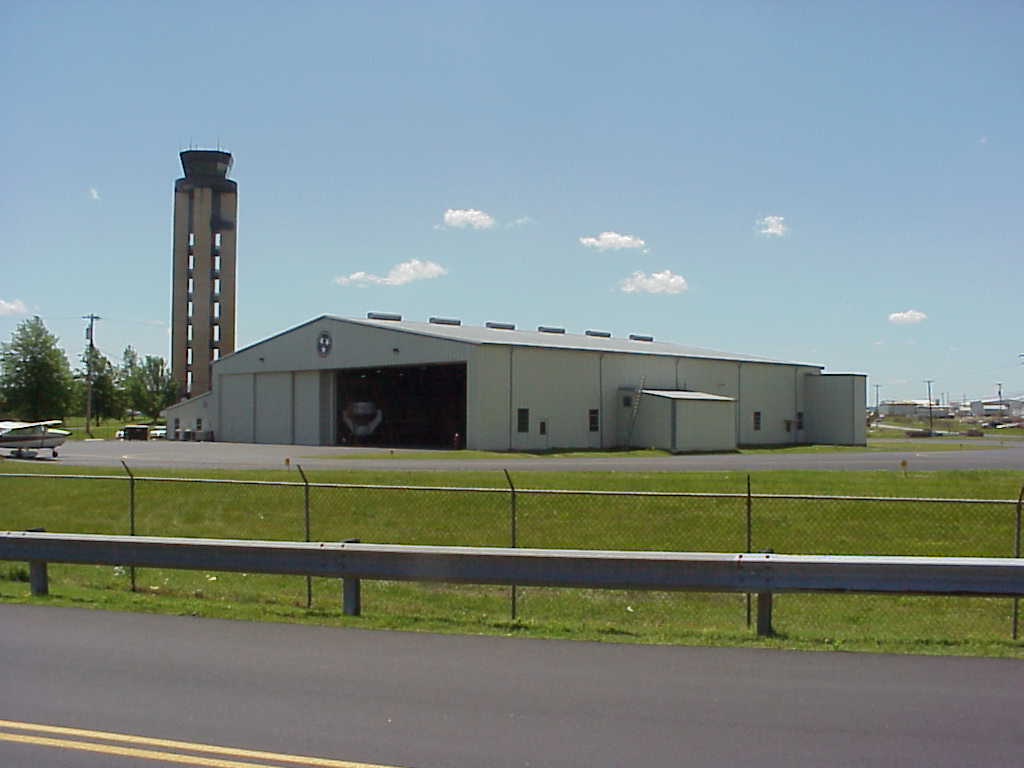
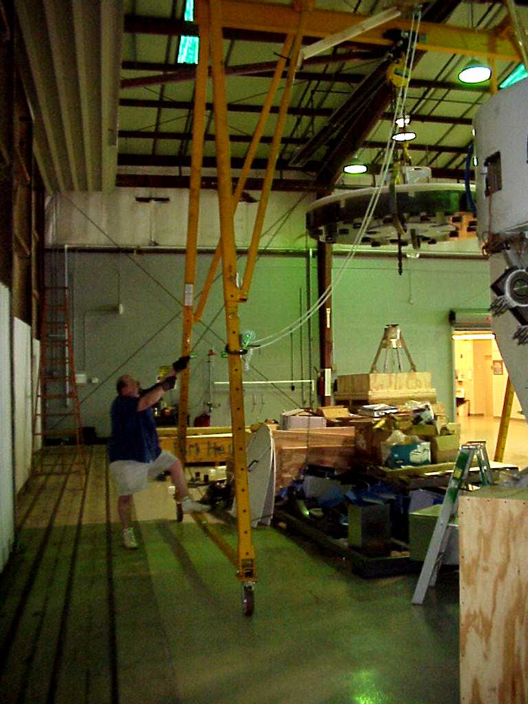
to Arizona, during the interval January, 1998, to June, 2000. We first
arranged for a space in the State of Tennessee's hanger at the Nashville
Airport for this purpose, later moving to the National Guard Armory.
- State of Tennessee Hanger,
site of telescope integration, and our
new site in the National Guard Armory.
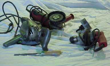
- Some essemtial tools for
telescope integration.
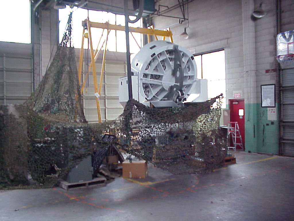
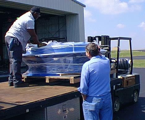
- Arrival of primary mirror,
January, 1998.
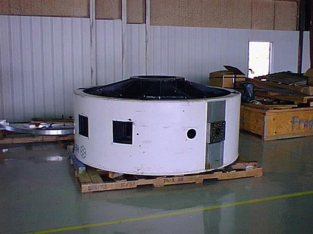
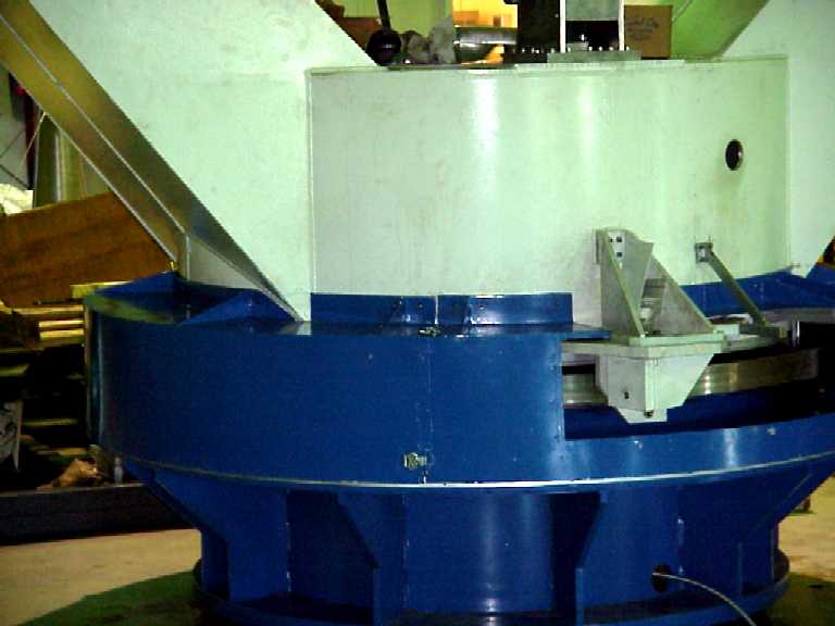
- Arrival of base,
March, 1998.
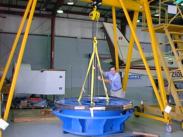
- Base with slewing ring
attached, July, 1998.
- Fork at airport
attached, July, 1998.
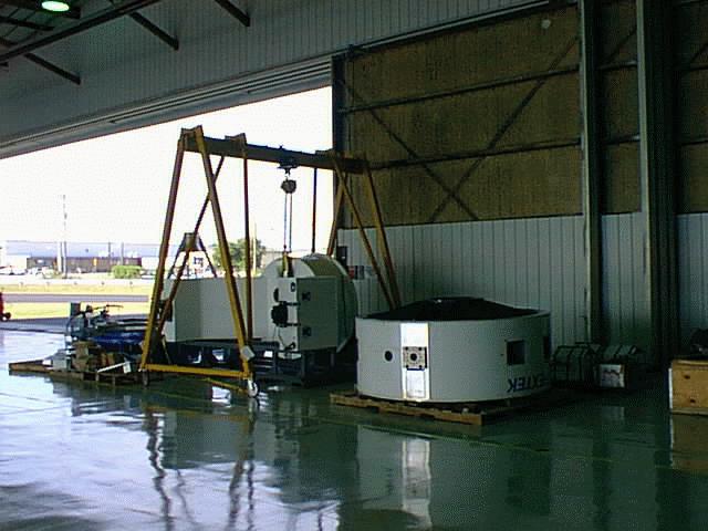
- All major parts
delivered, September, 1998.
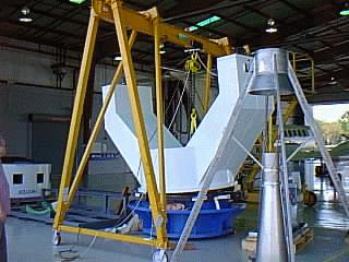
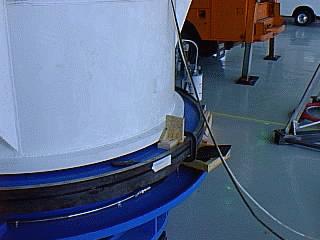
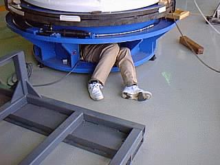
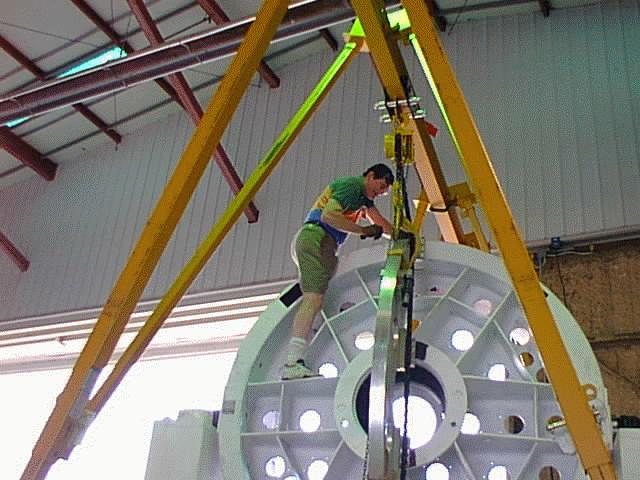
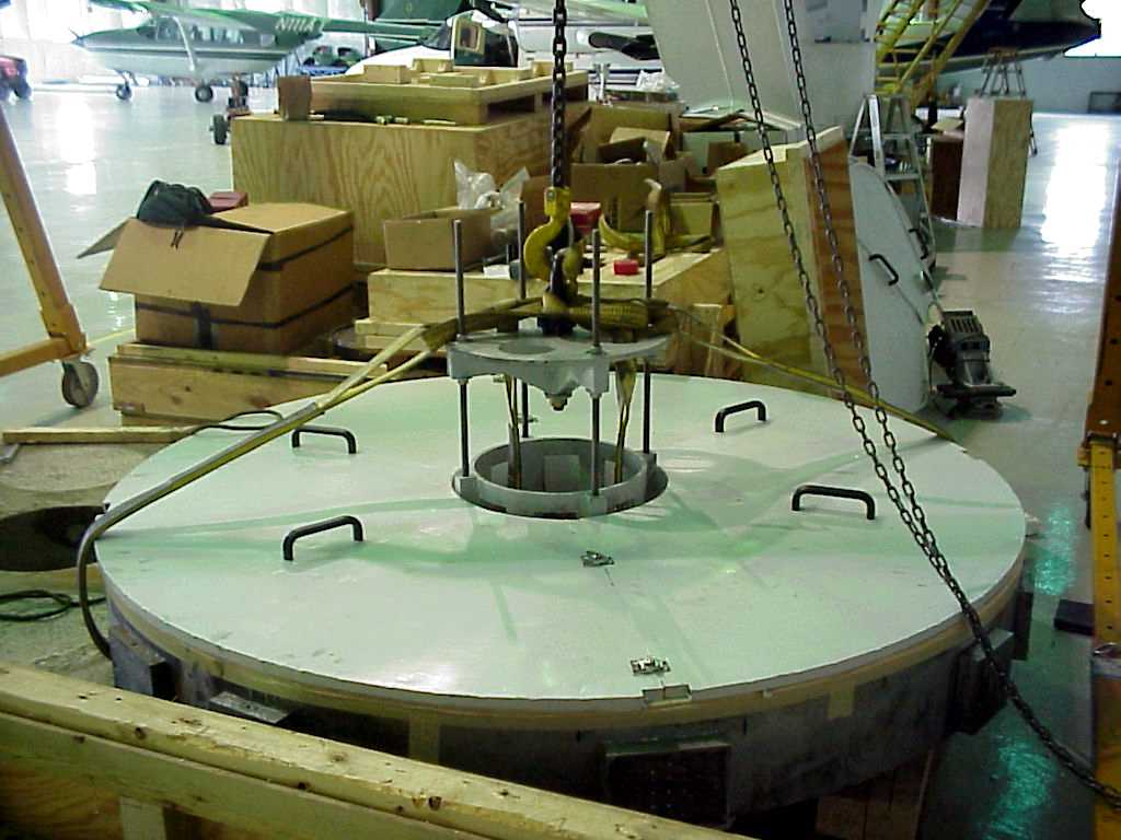
- Lowering fork onto base,
using alignment jig to center
on slewing ring, final lowering
onto oil pads, and Eaton and Henry
afterward, September, 1998.
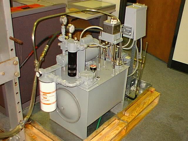
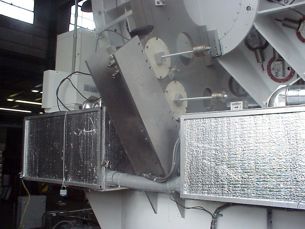
- Construction of oil pumping
system, at TSU campus, January, 1998.
- Detail of oil pump
showing tank and return pump, March, 1998.
- Telescope tube, with altitude
slewing sector in background, and
top end
(secondary-mirror support), September, 1998.
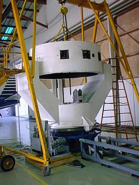
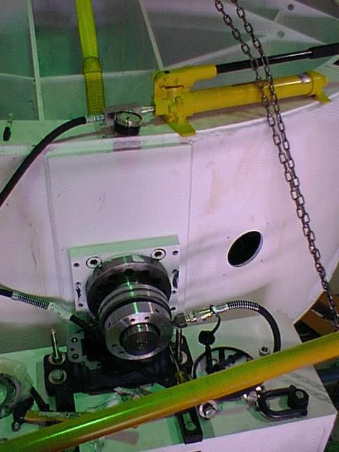
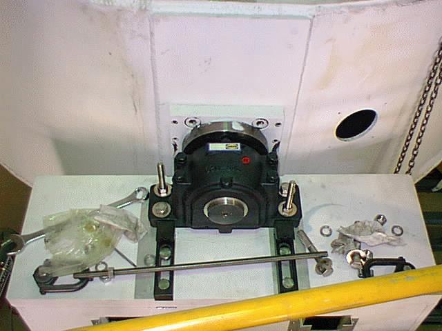
- Attachment of mirror cell (tube) 14-15 Oct. 1998:
Tube poised over fork ready
for attachment of bearings into
the pillow blocks to give
telescope structure.
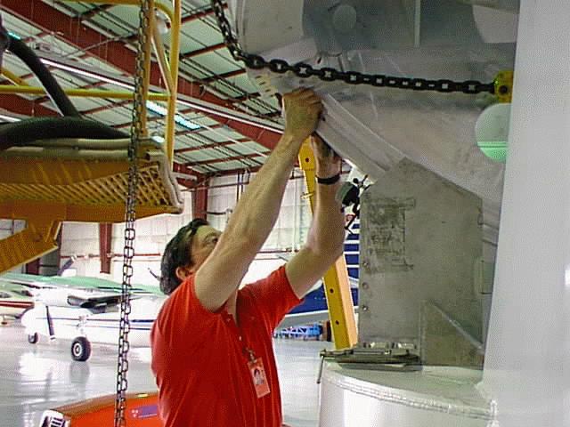
Detail of cell showing arrangement
of lifting slings.
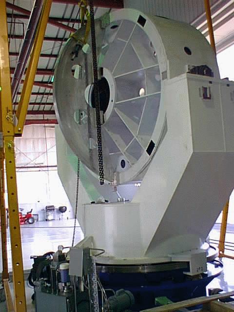
Another view of telescope
at this stage.
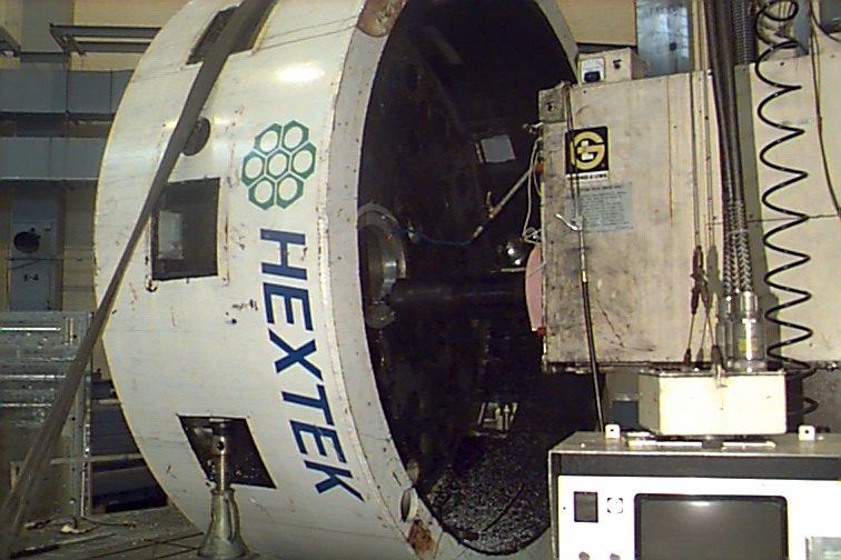
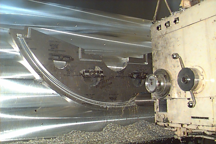
- Attachment of slewing sector for altitude 19-26 Oct. 1998:
Positioning of sector with crane,
and attachment to mirror cell.
Tube with sector in place.
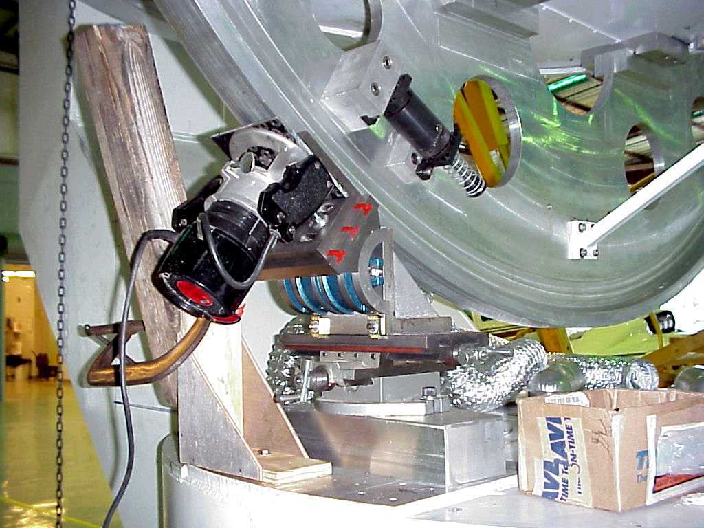
Measurement of runout
of slewing sector. Machine for
machining slewing sector in the telescope, April, 1999.
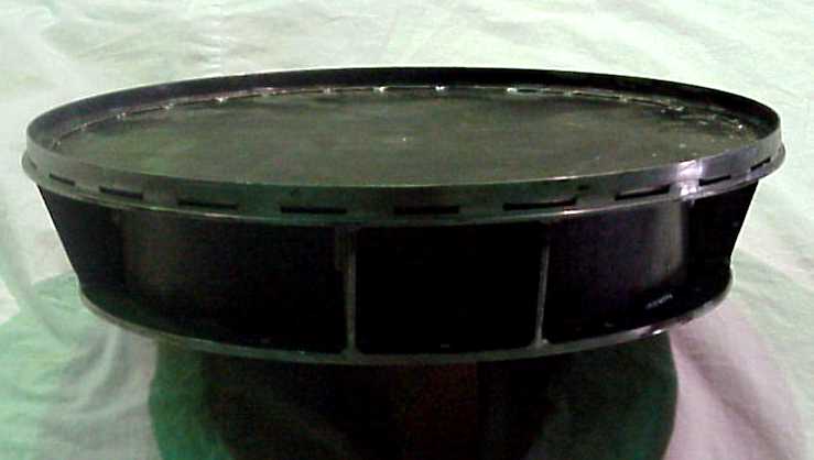
- Construction of base skirt 19 Oct.-Dec. 1998:
Framework for skirt,
from Hamilton Machine with some of the aluminum skin attached.
Skirt fitted onto telescope.
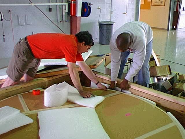
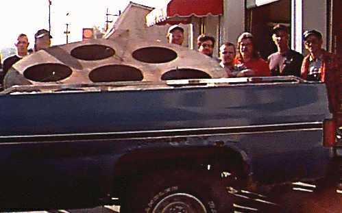
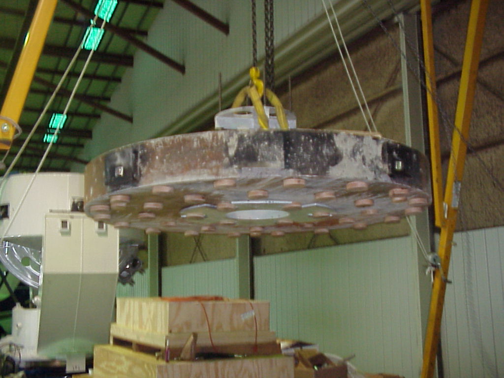
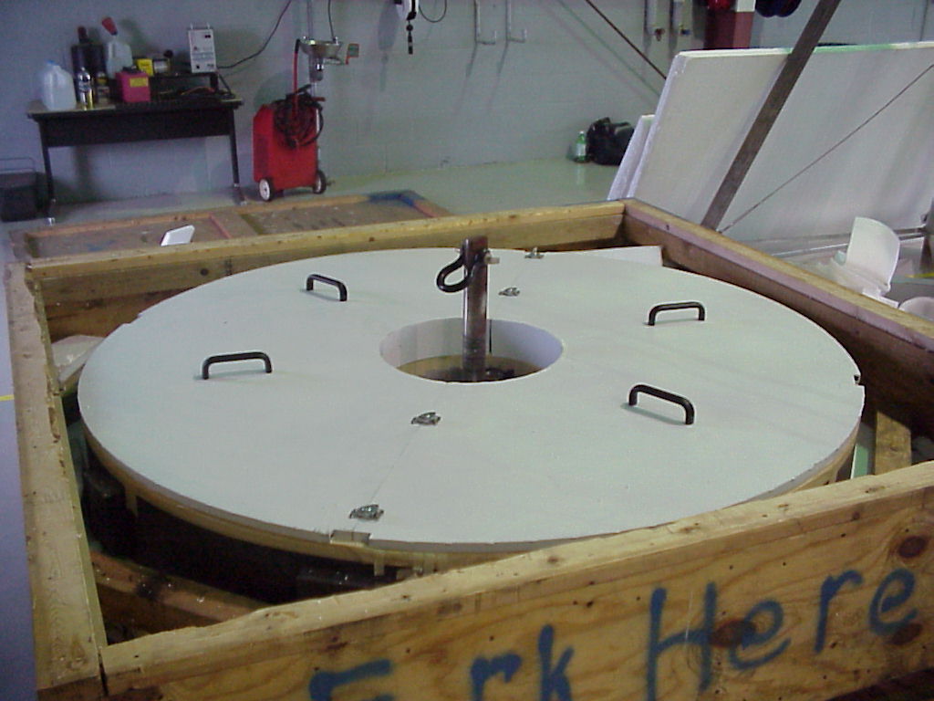
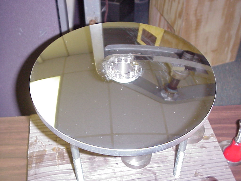
- Construction of surrogate mirror Nov./Dec 1998:
Measuring positions of pucks
on the real mirror.
Finished shell (Hamilton Machine) at The Collision Center of
Goodlettesville, TN, for adding lateral attachment points;
final version filled with concrete
(Merto Ready Mix) on the lifting fixture and lifting it
into telescope. Back of mirror cell showing
mirror-supports.
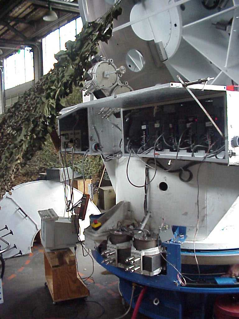
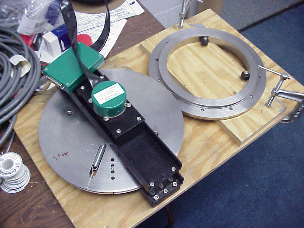
- Assembly of drives, Dec 1998/Feb. 1999:
Assembly of drive tractor at TSU
(mounting berings for the rollers with hydraulic press),
partially assembled tractor with
one of two motors in place, and
azimuth tractor in telescope.
Altitude tractor fitted up
for testing drive clamps.
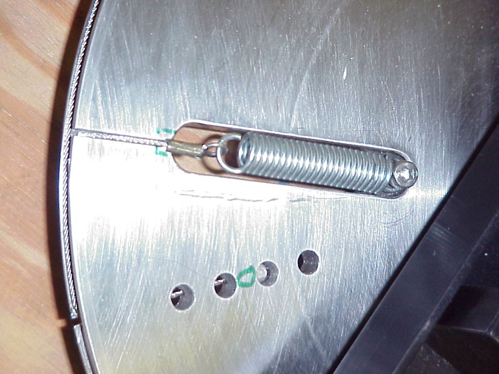
Testing motion in azimuth with manual controller. We have since
(April 2000) experimented with replacement of devices to tension the drive
tractors, which involved replacing the clamps with frames screwed rigidly
to the fork: New azimuth tensioner
in place and front view showing placement
of the tensioning springs. New altitude
tensioner in place and front view.
- Integration of top end (secondary-mirror holder), Jan/Feb 1999:
Top end (quadrapod) on fixture
for adjustment of baffle and after placing
in telescope.
- Placement of glass mirror in telescope, April/May 1999:
Mirror in box with cover from
Hamilton Machine and lifting fixture provided by Torus Optics.
On permanent lifting fixture.
Richard Tantaris lifting it into
into telescope.
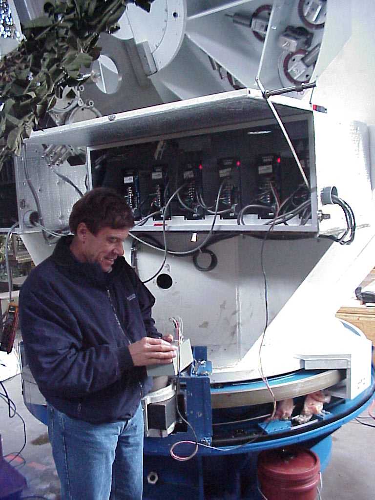
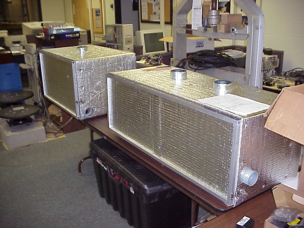
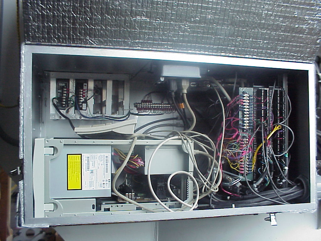
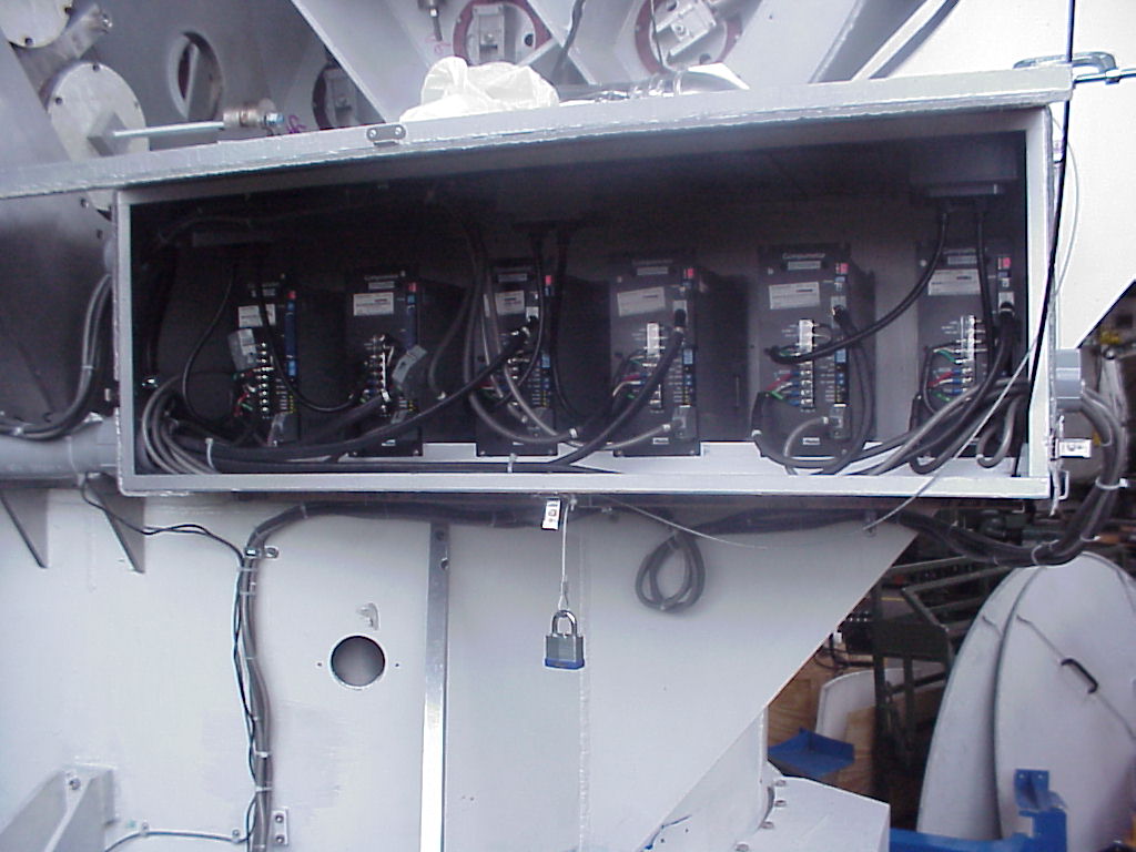
- Control electronics: Boxes for
electronics, made by Hamilton Machine and finished by TSU and
in the telescope. A view showing
wiring in main control box and in
box for servo amplifiers.
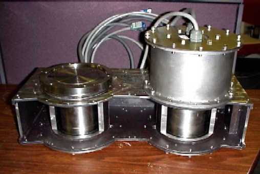
Construction of small parts
of the 2-m Telescope:
We assembled the secondary mirror cell, the instrument head, and
absolute encoder mounts in Nashville with the help of Mark Wells
of Huntsville, AL.
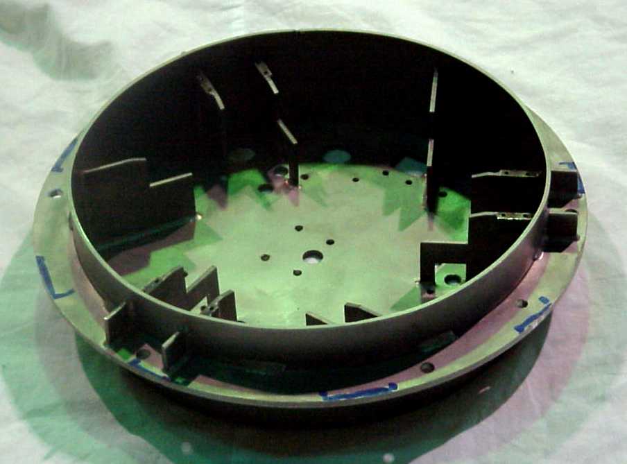
- Secondary mirror cell weldment
(from ORNL Y12) and with lever arms
for lateral movement of the mirror.
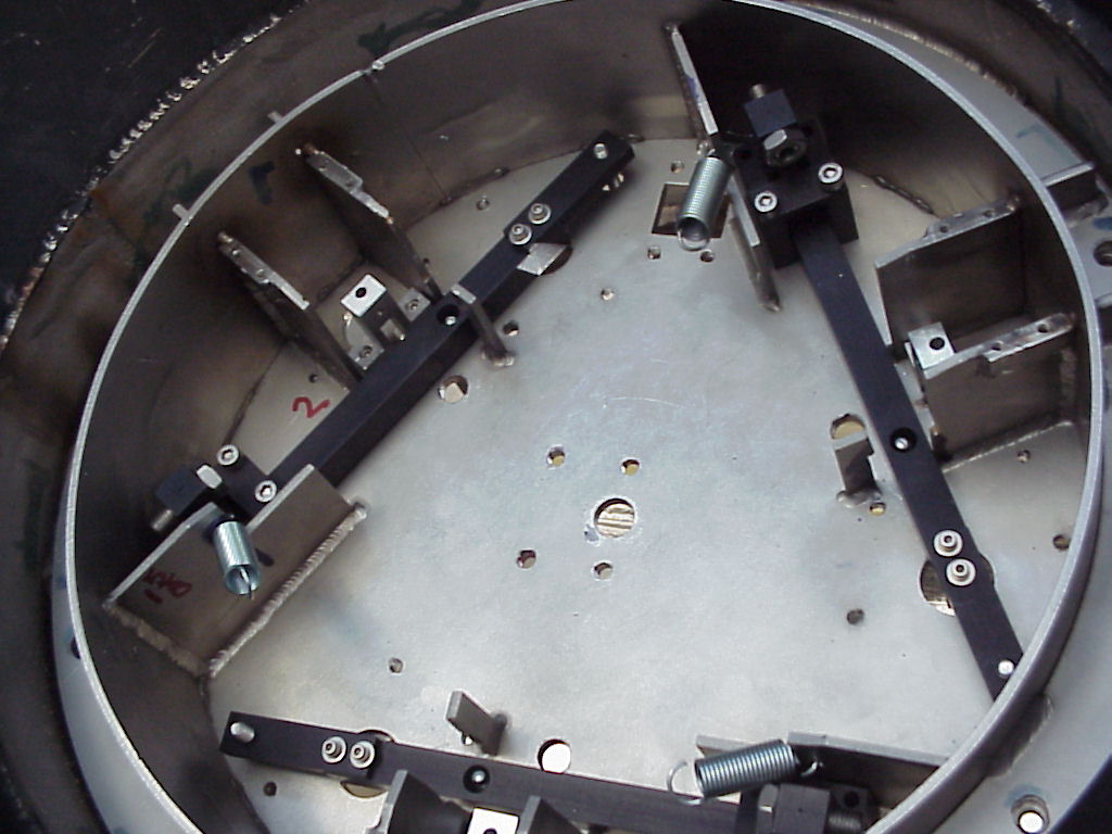
- Assembled cell showing tripod
to support the secondary mirror (mounted on invar stud); detail of
lateral link connecting tripod
to lever arm.
- Top view of cell showing
linear actuators to move the mirror.
- Secondary mirror glued to its stud
for attachment into the cell.
- Weldment for instrument head
(version for testing telescope) ain in place
in the telescope.
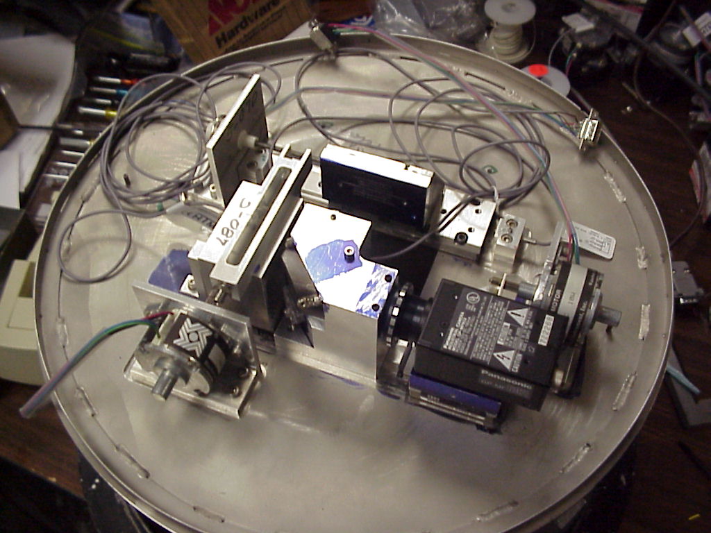
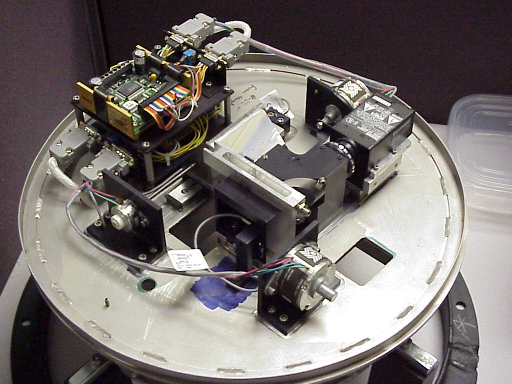
- Integration of instrument head:
test setup with focusing target in place of pickoff mirror and
later with pickoff mirror and
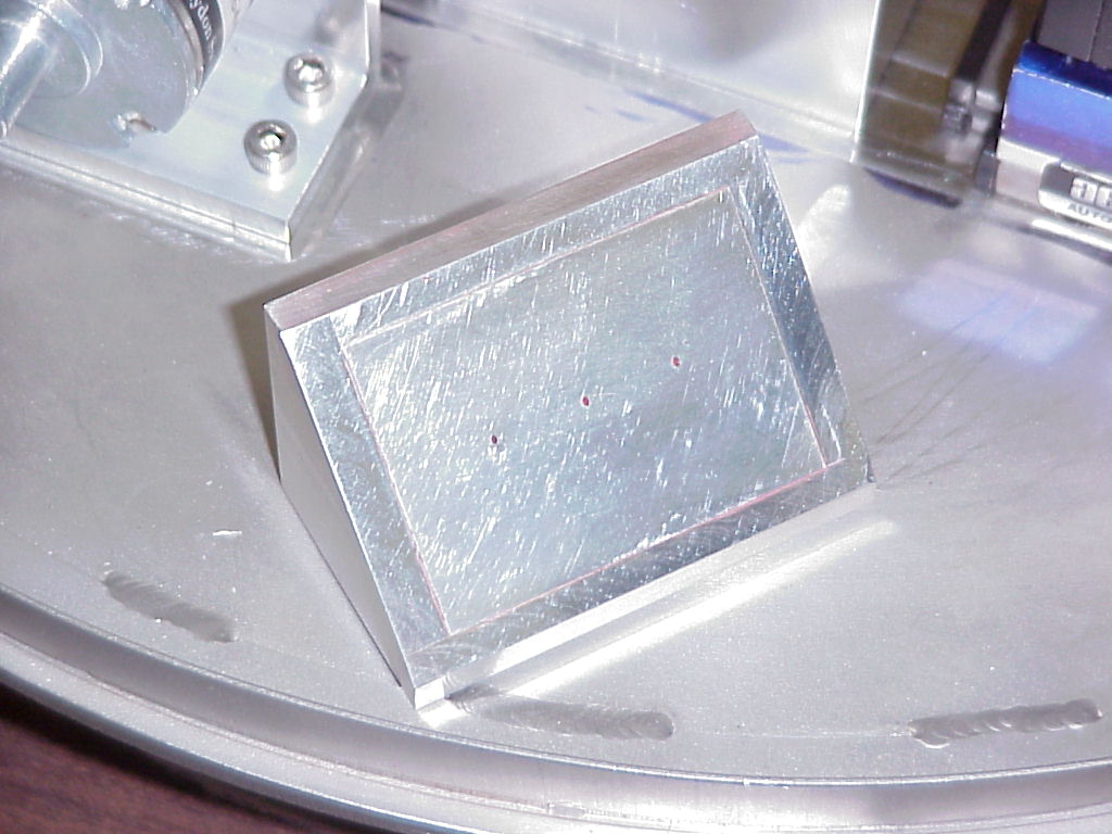
electrical connections finished. Partially polished prototype
pickoff mirror with holes drilled
for the fibers.
- Scheme for coupling absolute encoder
to azimuth axis, with attachment
and winding of coupling cable.
- M. Wells and M. Krebs have made most of the parts for the spectrograph,
such as the mount for the echelle grating, shown here in Wells' shop
for machining attachment points
for the fiber feeds and folding flat.