Application of Hydrostatic (Oil-Pad) Bearings to the Azimuth Axis of the TSU 2-m Telescope
TSU is building a 2-m telescope for high-dispersion spectroscopy. This telescope will have an alt-azimuth mount to use an existing mirror cell. Such a design requires some sort of large-diameter thrust bearing to carry all the moving weight of the telescope and to define a stable vertical axis for its motion. We considered several varieties of bearings for this application, including various types of slewing rings with ball bearings. These bearings typically have a coefficient of friction of order 0.003, which, although favorable, still requires torques near 200 lb-ft just to turn the telescope. An alternative, in which rollers push against the outer surface of a large horizontal ring, as in the WIYN or ARC telescopes, requires a very difficult scheme for controlling contact stresses in the ring with changing temperature. For these reasons, two types of hydrostatic bearing ultimately became the leading candidates for the telescope.
Hydrostatic bearings consist of a pair of machined surfaces between which a fluid is pumped. Pressure of the fluid supports the load and lubricates the bearing. Such bearings have several advantages in telescopes. (1) They have much lower friction than rolling bearings, since friction is provided only by the viscous shearing of the fluid. The resulting frictional torque required is usually insignificant. (2) Such bearings can be very stiff, especially with thin fluid films, and they perform at least as well as rolling bearings in this regard. (3) The materials from which hydrostatic bearings are made are usually readily available. (4) Tolerances for structures to mate with a hydrostatic bearing are no higher than for rolling bearings in practical designs.
Disadvantages of hydrostatic bearings for a telescope are the following: (1) Mating structures must be stiffer than for a rolling bearing if the hydrostatic bearing consists of three pads. Forces must be transferred through the few moving support points, while a ball-bearing slewing ring, for instance, supports its load around its full circumference. In practice, this disadvantage requires the base of the telescope fork to be especially stiff, but that base is typically the stiffest part of the telescope anyway. In the TSU telescope, the base is stiffened with two concentric rings of 1/2-inch aluminum plate. (2) A system for pumping fluid through the bearing must be maintained. (3) Considerable heat may be dissipated in the base of the telescope, which requires some means of cooling. The heating rate is simply the work required to pump the fluid against the resistance of the bearing,
For a bearing passing 0.5 in3/s at a 350 psi drop, the heat dissipated is 175 in-lbs/s, or 20 Watts. (4) The viscosity of practical fluids is appreciably temperature dependent. This means the flow rates can change markedly with temperature and that the relative pressure drops in different parts of the bearing system may be temperature-dependent.
The principles of hydrostatic bearings may be found in a number of good references. I have used a paper by Anderson (1964) and the standard reference book by Rippel (1963).
All hydrostatic bearings depend on the viscous resistance of fluids to flow through a restriction. For fluid flowing between two plates separated by a small distance h, the pressure gradient required to drive a flow of a given volume is given by the basic equation
where P is the pressure, l is a length along the direction of the flow, µ is the absolute viscosity of the fluid, w is the width of the flow, and dV/dt is the volume of fluid flowing per unit time. There are basically two types of hydrostatic bearings, based on the type of fluid used, liquid- and gas-lubricated bearings, but the equations used to describe them are exactly the same. The practical differences between gas and liquid bearings may be illustrated by comparing the viscosities of air and oil. For air, µ = 170 µp at 0 C, while for oil, µ = 100cp. This difference of 104 can be combined in Eq. (2) with some practical knowledge of fluid bearings to see how these two types of hydrostatic bearing differ. Oil bearings typically operate at pressures of several times those of air bearings, and air bearings may pass an order of magnitude greater volume of fluid. For these conditions, Eq. (2) predicts the gap in an air bearing would be about 15% the gap in an equivalent oil-pad bearing. Practical gaps are 0.0025 inches for the oil bearing and 0.0004 for the air bearing. In spite of using a compressible fluid, the air bearing is much stiffer because of its smaller gap, but the mechanical parts must be produced to correspondingly more stringent tolerances. This requirement is exacerbated by the larger size of the air bearing required for a given load by the smaller pressures.
A practical bearing requires several elements to work. There must be a pad through which fluid is pumped. It must have recesses into which the fluid flows and which develop the full pressure of the fluid as delivered to the bearing. These are surrounded by sills over which the fluid flows from the recess out of the bearing. It's in these areas that the fluid suffers a viscous pressure drop per Eq. (2). The width of these sills determines the flow rate, and if the pad were all sill, its flow rate would be minimized. However, recesses are required to apply sufficient force to pick up the load, since without fluid flowing through the bearing, the force is just the area of the recesses times the pressure of fluid delivered to the bearing without any flow. The sills must also be wide enough to support the applied weight without damaging the bearing when it is not pressurized.
To respond to changes in load, a fluid bearing must have some sort of regulator that changes the recess pressure in response to flow rate. In practice, this regulation is provided by the pressure drop of fluid flowing through a narrow (capillary) tube, per Eq. (2), or through an orifice. An alternative to the capillary tube is flow through the gap between two cylinders, a design used at Kitt Peak. For a narrow tube, the pressure drop is
where L is the length of the tube, and R is its radius. Flow between two cylinders may be found by direct application of Eq. (2):
where R is the mean radius of the two cylinders, and Delta R is the difference between them, i.e., the gap. For flow through an orifice,
where gamma is the weight density of the fluid and d is the diameter of the orifice. In all these schemes, greater flow gives a bigger pressure drop. Thus, when the applied force drops, the bearing separates, to give a greater flow per Eq. (2), therefore a bigger pressure drop in the regulator and a smaller force on the load. Similarly, if the bearing is loaded more heavily, the oil gap is squeezed thinner, reducing the flow, and thus giving a lower pressure drop in the regulator and a higher recess pressure in the bearing.
For practical bearings, the compensation is is designed to provide enough reserve pressure to respond to the greatest loads expected.
Components of the system are illustrated in the attached drawings. I shall discuss the design of the various elements in the following paragraphs. The supported weight of the telescope is assumed to be 13,500 lbs (4500 lbs/pad). For a wind speed up to 55 mph, the loading on any one pad varies over the range 2000 - 6500 lbs. Pressure supplied by the oil pump is nominally 420 psi with a drop of less than 5 psi in the supply lines.
Pads: These are a standard design, a 2x3 rectangular pad with four recesses. Properties of this pad are given by Rippel (1963) on page 14. Our actual dimensions are slightly greater than 4x6inches, which gives room for slightly wider sills. The sills are about 0.6 inches wide, with an area of about 10 in2 or a pressure on the supported journal of 450 psi. The recesses are roughly 1.35x2.35 in, or 12.7 in2, which gives a force of 5300 pounds at zero flow. This should be sufficient for picking up the telescope when the oil is turned on. The sills are flat to 0.0005 inches and smooth to 60 microinches. Figure 1 is a drawing of the oil pad and its support. Figure 2 shows an outline of the pad.
The force developed for a pad geometry is the recess pressure times an effective area. For the geometry we have chosen, the effective area is roughly the area of the recesses and any internal sills separating them plus one-half the area of the outer sills. For the dimensions we have chosen, this comes to 23.5 in2, about 78 % of the actual area of the pad. With the pressures specified, we can expect each pad to support up to 9400 lbs, about 2800 lbs higher than the loading expected under our most extreme operating conditions.
Fluid: The bearing is designed to operate on oil with a viscosity near 100 cp (1.4 x 10⁻⁵ lb-s/in2) and specific gravity near 0.9 (gamma=0.033 lb/in3). The oil may need to be changed with season to maintain viscosity in the range desired. Originally, we planned to use a Mobil industrial oil (SHC 626) with properties somewhat better than a multi-viscosity automotive motor oil. The system designed will require about 10 gal of oil. We have since decided to switch to 10W-40 motor oil, at least for cooler weather, because of the lower price. The stuff seems to work even at 90-100F during summer tests, but it picked the telescope up only half as much as desired with the designed flow rate.
Compensation:We have considered several ways of compensating the bearing, deciding eventually to use a single orifice in each recess with a d=0.0138 inch aperture for a pressure drop of appx. 175 psi at the ambient flow rate.
Originally, we had intended to use a two-stage system, with primary compensation through a single capillary tube (d=0.047 in, L=2 in) at the input of each bearing pad, which will give a drop of about 175 psi for an ambient flow rate of 0.75 in3/s, and an orifice to compensate each of the four recesses independently (d=0.020 in to give DeltaP=40psi@0.2 in3/sec).
A possibly better alternative to both these schemes might be linking each recess separately to an input manifold with appx 8 inches of 0.047-in tube. This arrangement would allow each recess separately to be fully compensated, eliminate the complicated internal oil passages, and give more room around the edges of the bearing for oilreturn channels.
Pressures: Supply pressure: 420 psi; ambient recess pressure: 206 psi; exhaust pressure: 15 psi. These values will be established by adjusting the oil pump.
Flow Rate: Ambient flow rate is 0.6 in3/s per pad, at a separation of 0.0022 in, or 1.8 in3/sec for the whole bearing. This rate is regulated by a flow-control valve on the oil pump.
Ehaust Speed: At the ambient flow rate, the gap is 0.0025 inches thick and 20 inches long, which gives a speed of 1 ft/s.
Oil Distribution System: Oil will be distributed to the various pads through 0.5-in ID stainless-steel tubing. Pads will be connected to this distribution tube by hydraulic hoses approximately 18 inches long. Under ambient conditions, the longest run at full volume is 100-150 inches, for which the pressure drop in the supply lines is expected to be of the order of 3 psi.
Oil Return System: Oil will return to the pump through a series of channels around the outside of the pads, sealed with oil-resistant rubber gasket, which feed 3/4-inch return lines under gravity. Each pad will have two such exhaust lines feeding into a manifold in the inside of the telescope base. With a head of 20 inches, the resulting 0.66 psi pressure drop will drive a return flow of only 1.7 in3/s, and is probably not enough to drive the return flow through the return filters. We therefore anticipate using a scavenger pump to exhaust the return line. This second pump will give a flow of 10 in3/s at 10 psi, 7 in3/s from the reservoir and 3 in3/s from the bearing pads. The full reservoir would be pumped through the return filter every 6 minutes. The oil distribution and return lines are shown in Figure 3.
Oil Pump: Pumps for hydrostatic bearings can vary significantly in sophistication. Heaters and coolers can be provided to regulate the oil's temperature, hence its viscosity, within narrow ranges. However, very simple systems with a minimum of such regulation seem to work well for the smaller telescopes at Kitt Peak National Observatory.
TSU has purchased an oil pump from Robbins and Bohr, an industrial supplier in Nashville/Chattanooga, which consists of a low-capacity constant-volume displacement pump from Bosch, followed by pressure and flow regulators. A high pressure filter screens out particles bigger than 10 µm (0.0004 in), about 1/6 the expected separation of the bearing plates. A water filter and another grit filter to protect the pump are provided in the return line. Because of the low gravity head in the return line (about 0.6 psi) a second pump is requirred to suck the oil out of the system. To keep this pump from cavitating, we provide a parallel intake from the oil tank. This provides continuous recirculation, cleaning, and cooling of the oil.
Anderson, W.J. 1964, in Advanced Bearing Technology, ed. E.E. Bisson and W.J. Anderson, NASA SP-38, p. 97.
Rippel, H. C. 1963, Cast Bronze Hydrostatic Bearing Design Manual, (Cleveland, OH: Cast Bronze Bearing Inst.).
Viscosities of oils are measured in various units that would be obscure to the typical astronomer, so here's a tutorial. Dynamic (absolute) viscosity is measured in Poise in the cgs system (1 Poise = g/cm-s = 6.89 x 10⁴ lb-s/in4). Kinematic viscosity, which is sometimes quoted for fluids, is just dynamic viscosity divided by density the density. In the CGS system, kinematic viscosity is measured in Stokes (1 Stoke = 1 cm2/s). Since the density of the typical oil is 0.85--0.9, dynamic and kinematic viscosities are essentially equal, especially compared to the temperature variations expected in a hydrostatic bearing operating in a telescope. The temperature variation of viscosity is measured by a viscosity index (VI); the bigger VI, the smaller the temperature variation. A third quantity of interest for hydrostatic bearings in telescopes is the pour point of the oil. The lower the pour point, the easier it is to pump it in cold weather.
We decided to use a synthetic oil, such as a top-of-the-line motor oil, in the oil pump because such oils have a large viscosity indexes, low pour points, and moderate prices. They may be obtained with a range of viscosities, as well. Mobil SHC lubricants (designed for industrial gearboxes operating in extreme conditions) can be ordered with viscosities in the range 32-1000 cS at 40 C with VI on the range 138-170. Castrol SYNTEC 5W-50 synthetic motor oil has a viscosity of 121 cP at 40 C with VI=175 and a pour point of -54 F.
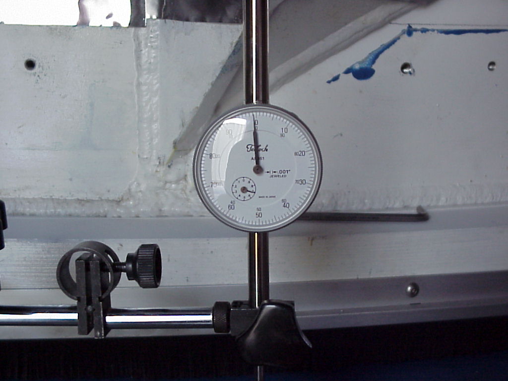
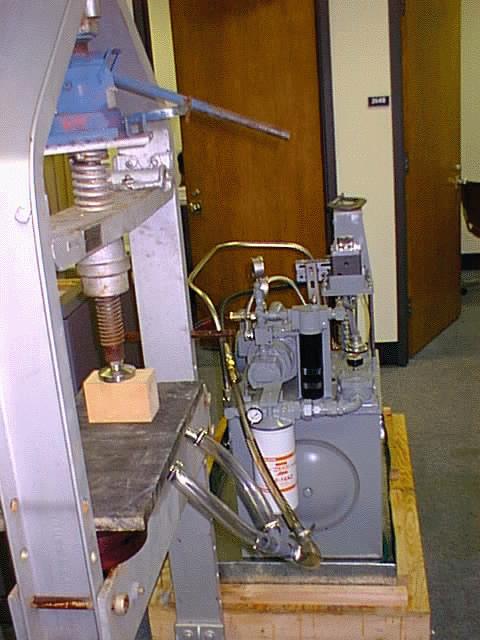
To test the qualities of the oil pads and suitability of potential oils, we have conducted pumping experiments. By measuring the flow rate for a given restriction, we can determine the viscosity of the oil in service, estimate the temperature rise expected in the oil system, and verify the design of the compensation system. Also, by setting up the oil pad in a press spring, we may verify its behaviour over the full range of loading expected before putting it in the telescope. The setup for the pumping tests is shown in Figure 4. The setup for a test to verify operation of the pad is shown in Figure 5.
In the first test, we verified the flow rate of the Bosch gear pump, which filled a 1-liter Coke bottle (kindly donated by M.R. Busby) in 6 sec, or 10 in3/s, as expected. We then set up the system to pump oil through a 4.0-inch length of d = 0.047 inch tube at a pressure drop set by the relief valve. This gave a flow of 0.64 in3/s at 365 psi, corresponding to an absolute viscosity of 120 cP at 20 C. Later tests verified the working of the flow regulator valve, which maintains a constant flow rate with changing pressure. We verified Eq. (5) by punping oil through a 1-mm diameter (0.039 in) hole drilled in the end of a plug (flat ended set screw), finding a flow of 1.5 in3/sec at a pressure drop of 185 psi, which is within the prediction of Eq. (5) to within 10 percent.